x404.co.uk http://www.x404.co.uk/forum/ |
|
Circuit design help http://www.x404.co.uk/forum/viewtopic.php?f=3&t=15249 |
Page 1 of 1 |
Author: | cloaked_wolf [ Sat Nov 26, 2011 9:53 pm ] |
Post subject: | Circuit design help |
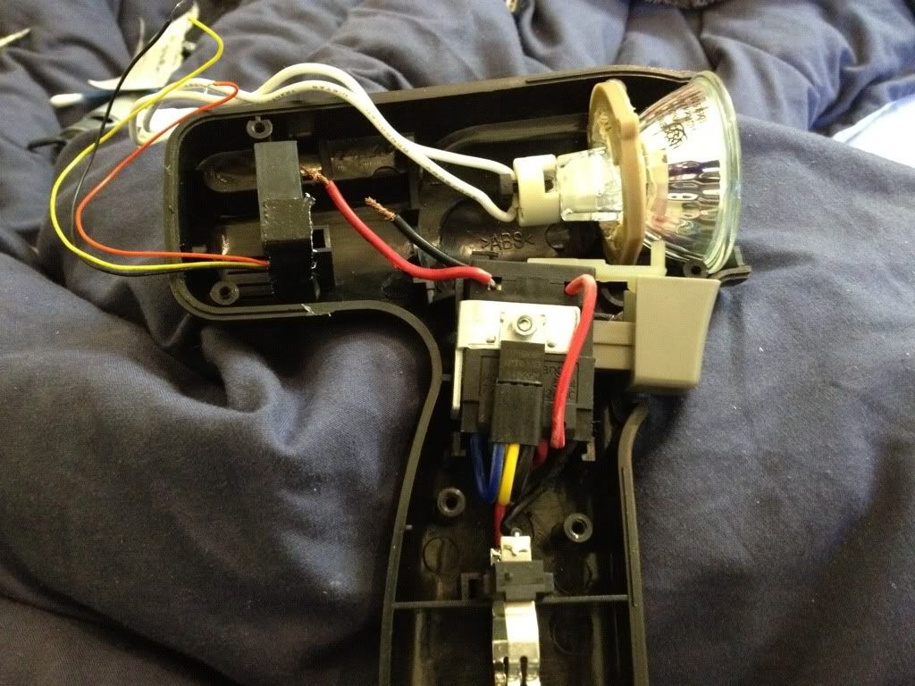
Okay, I've made my own sungun using a 14.4 cordless drill. Ripped out the motor and replaced it with a halogen downlight bulb. It works great (or at least it did until I dropped it. Don't know whether I've shorted the battery or something as replacing the bulb doesn't work). What happens is you squeeze the trigger and the bulb lights for as long as you keep the trigger squeezed. It's also a variable trigger so the intensity of the light increases as you squeeze the trigger. This works great except because I'm using a 50W bulb, the entire thing can get pretty hot. ![]() 
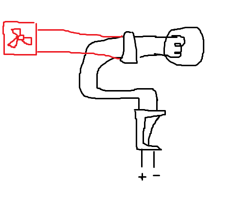
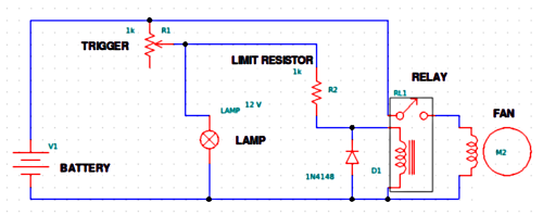
What I envisage is adding in a PC mobo/CPU fan to the back of the drill but before the vents so it'll suck in cool air. The problem is do I add it in series or in parallel? Now, it's been something like fifteen years since I did GCSE Electronics. From what I remember, adding in series means the voltage is divided between the bulb and fan and hence less current is drawn across each device, which would mean a dimmer bulb and underpowered fan. Or I could do it in parallel which means the voltage across each component is the same so they should both work equally well. Or am I completely wrong? |
Author: | JJW009 [ Sun Nov 27, 2011 1:15 pm ] |
Post subject: | Re: Circuit design help |
Parallel, as per your diagram. If you put it in series, the bulb wouldn't get enough currant to even glow. Note, the fan may not start at low voltages. Probably not a problem though. |
Author: | Linux_User [ Sun Nov 27, 2011 1:35 pm ] |
Post subject: | Re: Circuit design help |
Here's a bit more currant for you: ![]() ![]() |
Author: | JJW009 [ Sun Nov 27, 2011 1:38 pm ] |
Post subject: | Re: Circuit design help |
Not sure they're the right polarity, unless you want them to light up black on a black background. Here's some AC currants: ![]() |
Author: | cloaked_wolf [ Fri Dec 02, 2011 2:38 pm ] |
Post subject: | Re: Circuit design help |
Okay guys, so it works. Got the fan working. Sits forwards of the vents and sucks air in. Only problem is that it requires a full squeeze of the trigger to go at full pelt. The trigger is a variable resistor, essentially, so a half-squeeze gives half the output and a full-squeeze gives the full lot. I want the fan to remain at full power. Any ideas? Only thing I can think of is a separate switch and connect the fan directly to the battery. |
Author: | belchingmatt [ Fri Dec 02, 2011 2:46 pm ] |
Post subject: | Re: Circuit design help |
The trigger mechanism should just be based around a potentiometer. That should have three contacts, you only need to play around to find the right two to give you constant power to the fan, but it would be on all of the time the battery was inserted. IIRC |
Author: | John_Vella [ Fri Dec 02, 2011 2:56 pm ] | |||||||||
Post subject: | Re: Circuit design help | |||||||||
The simplest solution is sometimes the most effective. I would have a seperate switch for the fan, but don't forget to switch it on before you squueze the trigger for the lamp. |
Author: | cloaked_wolf [ Fri Dec 02, 2011 2:59 pm ] |
Post subject: | Re: Circuit design help |
I've got two batteries now because I bought a whole new kit - new drill, new bulbs and new connector. So not concerned about battery power. Just wondering what the drain would be like on such a thing? It's only a 30mm or so mobo fan. |
Author: | Fogmeister [ Fri Dec 02, 2011 3:02 pm ] | |||||||||
Post subject: | Re: Circuit design help | |||||||||
I was going to suggest something similar until I realised that it would cause it to be on permanently. How about sticking a transistor in it attached to the resistor... OK, I'll have to describe this... Wire the fan in parallel with the entire trigger/resistor/light section. Half way along the negative wire of the fan wire in the collector-emitter sides of a transistor. Then wire the base of the transistor to the positive side of the resistor. I have no idea if this is correct but from reading stuff I think this should work. Essentially the transistor is acting as a switch to the fan. When the transistor recieves even a tiny bit of current through the base it will turn on and allow a full flow of current through the collector - emitter. This way the trigger will vary the current going through the light but act as a binary switch for the fan. ... ... or something. |
Author: | rustybucket [ Fri Dec 02, 2011 5:12 pm ] |
Post subject: | Re: Circuit design help |
I'll draw you a diagram - hang on a minute. [Edit] This is what I'd do. ![]() Don't take the values too literally:
|
Author: | Fogmeister [ Fri Dec 02, 2011 7:49 pm ] |
Post subject: | Circuit design help |
Ok, that's what I was aiming for I just hadn't heard of relays before. The idea is the same though. The small current from the variable resistor activates a switch to turn the fan on. |
Author: | cloaked_wolf [ Fri Dec 02, 2011 8:37 pm ] |
Post subject: | Re: Circuit design help |
There's not much room to play around with: ![]() |
Author: | belchingmatt [ Fri Dec 02, 2011 9:54 pm ] |
Post subject: | Re: Circuit design help |
You could get a bus through there. |
Author: | cloaked_wolf [ Fri Dec 02, 2011 10:07 pm ] |
Post subject: | Re: Circuit design help |
The wires at the top have been taped down to maximise air flow from the fan. |
Page 1 of 1 | All times are UTC |
Powered by phpBB® Forum Software © phpBB Group https://www.phpbb.com/ |